Introduction
Due to unavoidable manufacturing tolerances, the mechanical setting of machines with the same type number, may differ in detail. However when the machines a reset in accordance with the procedure the soldering process settings are comparable.
Procedure
1. Level the solderpot in the direction of the length of the machine frame.
2. Level the top of the Smart Wave nozzle.
Note: A "built in" control is possible by starting the solder pump and reducing the pump speed until the solder flow is breaking from the nozzle rim. At this point the solder must break evenly over the width of the nozzle.
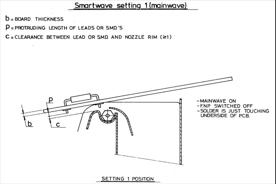
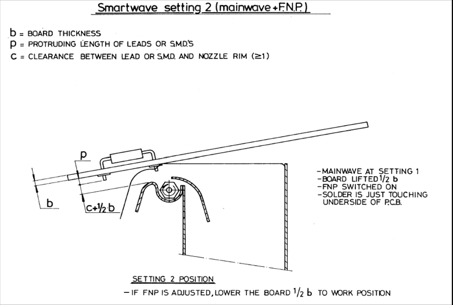
3. Adjust the distance between the nozzle rim, and the inside of the finger V-grooves to S = p + c + ½b, (S > 8mm) (p= protruding length of leads or SMD's on the solder side, c= clearance 1-2 mm, b= printed circuit board thickness).
Note: For a solderpot provided with a supporting skate. Set S at about 8 mm, Control and, if necessary, adjust the setting by running a PCB with supporting pins via the conveyor over the skate and check if the board is not bending, a very slight sagging may be allowed. Adjustments can be made by correcting the conveyor- or solderpot setting.
4. Put the glass plate in the measuring carrier and convey the carrier above the solderpot nozzle and set the main solder pump so that the solder just touches the glass plate (setting MP).
5. Check if the glass plate is touched evenly over its full width.
6. When the Smart Wave must operate as a bi-directional wave during soldering, the back plate must now be so adjusted, that the solder will just not flow over the back plate.
7. Set the glass plate at a distance 1/2 - 3/4b, e.g. with help of adjusting strips, in the measuring carrier. Set the main wave on the "MP" setting and switch on the front nozzle pump (FNP) and adjust till solder is just touching the glass plate over its full width (setting FNP).
Production setting of the Smart Wave
If we set the Smart Wave in accordance with the procedure, we are certain that no solder will flood over the component side of the boards, assuming that the sagging of the boards is compensated. At this setting however the necessary liquid pressure needed to wet all SMD pads, may be insufficient, leaving skipped joints. This also depends on the conveyor speed and the flux system used. A higher wave pressure, which may be necessary, can only be applied when the printed circuit boards have no holes except for mounting components. If the boards are soldered without the use of a pallet (carrier) then a higher wave setting can only be applied if the front nozzle pump is switched on and off depending on the position of the board in the conveyor. This can be accomplished with the tracking system.